In this fourth instalment of the ‘How a Turbo Works’ series – Part 4, we discuss what and how the wastegate works.
How a Turbo works – Wastegate
The compressor turbine wheels job is to spin drawing in vast volumes of air. This goes into the engine and the turbocharger’s output exceeds the engine’s air pressure. This unequal balance is what produces boost – read part 3 in this series to learn more about how boost is produced.
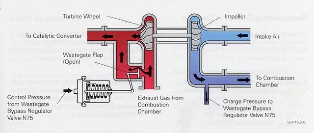
But since a turbo can spin far beyond what is safe, the speeds restricted by the wastegate.
The wastegate is a common way to control the speed of something within a system. This can be further expanded by an electronic boost controller. The introduction of a wastegate allows the exhaust gases to bypass the turbine.
In this third instalment of ‘How a Turbo Works’ series – Part 3, we discuss specifically the boosting potential a turbo can give a car and tease the wastegate -more on that in part 4.
How a turbo works -Boost
Boost/thrust refers to the increase in pressure within the manifold. This is the level of thrust can be read by looking at the pressure gauge within the instrument panel. This is usually translated into bar, psi or kPa. The pressure reading is representative of the extra air pressure that is achieved over what would be achieved without the forced induction.
‘The typical boost provided by a turbocharger is 6 to 8 pounds per square inch (psi)… Therefore, you would expect to get 50% more power.’
Boost is limited by controlling the wastegate. This wastegate stops the exhaust gases from crossing over. In some cars, the maximum boost depends on the fuel’s octane rating and is electronically regulated using a knock sensor or Automatic Performance Control (A.P.C.).
Many diesel engines do not have any wastegate because the amount of exhaust energy is controlled directly by the amount of fuel injected into the engine.
In this second instalment of ‘How a Turbo Works’ series – Part 2, we discuss the various parts of a turbo and how they all play an important role in producing more power.
Components
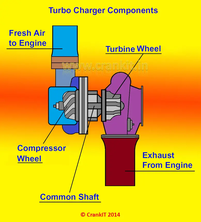
For a turbo to work it has to have four main components listed below and illustrated.
Turbine wheel
Compressor/Impeller wheel
Center Hub Rotating Assembly (C.H.R.A.)
Canonical housing
The turbine and impeller wheels are housed at opposite sides of the Centre Hub Rotating Assembly. This is also known as the C.H.R.A.
The housings fitted around the compressor and turbine wheels suck in and direct the gas through the turbo. The size and shape of the wheels dictate the performance characteristics of the overall turbo.
Often the same basic turbocharger assembly will be available from the manufacturer with multiple AR* choices for the turbine housing and sometimes the compressor cover.
We mentioned earlier the turbine and impeller wheels ‘size and shape of the wheels dictate the performance’. Generally, the larger the turbine wheel and compressor wheel, the larger the flow capacity. Measurements and shapes can vary, as well as curvature and the number of blades on the wheels all introduce a varying factor as to how well the turbo will perform.
‘size and shape of the wheels dictate the performance’
The Centre Hub Rotating Assembly (C.H.R.A.) houses a single shaft that connects and suspends the compressor and impeller wheels. At the rotating speeds the turbo wheels spin, bearings are necessary to have it rotate with minimal friction. This is usually performed by a thrust or ball bearing lubricated by a constant supply of pressurized oil. The C.H.R.A. can also be “water-cooled” by allowing the engine coolant to be circulated in place of oil.
How a turbo works are down to the principles of design. This series of articles will attempt to explain the principles of those designs.
A turbocharger consists of a turbine and a compressor linked by one shared and central axis. The turbine inlet receives exhaust gases from the engine exhaust manifold causing the turbine wheel to rotate. This rotation drives the compressor, compressing ambient air and delivering it to the air intake of the engine.
The Objectiveof how a turbo works
The objective of a turbocharger is to improve upon the size-to-output efficiency of an engine by solving for one of its cardinal limitations. A naturally aspirated car engine uses only the downward stroke of a piston to create an area of low pressure in order to draw air into the cylinder. Since the number of air and fuel molecules determines the potential energy available to force the piston down on the combustion stroke, and because of the relatively constant pressure of the atmosphere, there ultimately will be a limit to the amount of air and consequently fuel filling the combustion chamber. This ability to fill the cylinder with air is its volumetric efficiency. Since the turbocharger increases the pressure at the point where air is entering the cylinder, and the amount of air brought into the cylinder is largely a function of time and pressure, more air will be drawn in as the pressure increases. The intake pressure, in the absence of the turbocharger determined by the atmosphere, can be controllably increased with the turbocharger.
Application of how a turbo works
The application of a compressor to increase pressure at the point of cylinder air intake is often referred to as forced induction. Centrifugal superchargers operate in the same fashion as a turbo; however, the energy to spin the compressor is taken from the rotating output energy of the engine’s crankshaft as opposed to exhaust gas. For this reason turbochargers are ideally more efficient, since their turbines are actually heat engines, converting some of the kinetic energy from the exhaust gas that would otherwise be wasted, into useful work. Superchargers use output energy to achieve a net gain, which is at the expense of some of the engine’s total output.
Found the answer you were looking for… take a look at our eBay store to purchase the equipment you need. Click here to go to our eBay store
This website uses cookies to improve your experience. We'll assume you're ok with this, but you can opt-out if you wish. Cookie settingsACCEPT
Privacy & Cookies Policy
Privacy Overview
This website uses cookies to improve your experience while you navigate through the website. Out of these cookies, the cookies that are categorized as necessary are stored on your browser as they are essential for the working of basic functionalities of the website. We also use third-party cookies that help us analyze and understand how you use this website. These cookies will be stored in your browser only with your consent. You also have the option to opt-out of these cookies. But opting out of some of these cookies may have an effect on your browsing experience.
Necessary cookies are absolutely essential for the website to function properly. This category only includes cookies that ensures basic functionalities and security features of the website. These cookies do not store any personal information.
Any cookies that may not be particularly necessary for the website to function and is used specifically to collect user personal data via analytics, ads, other embedded contents are termed as non-necessary cookies. It is mandatory to procure user consent prior to running these cookies on your website.
Functional cookies help to perform certain functionalities like sharing the content of the website on social media platforms, collect feedbacks, and other third-party features.
Performance cookies are used to understand and analyze the key performance indexes of the website which helps in delivering a better user experience for the visitors.
Analytical cookies are used to understand how visitors interact with the website. These cookies help provide information on metrics the number of visitors, bounce rate, traffic source, etc.
Advertisement cookies are used to provide visitors with relevant ads and marketing campaigns. These cookies track visitors across websites and collect information to provide customized ads.
The old premises will still be functioning as normal from 8.30 am to 4.30 pm and we can still be contacted on: 01772 697979 or by email to sales@turboforce.co.uk for any enquiries.